I finally finished this mod. It works, and sounds fantastic. Long story definitely
*not* short, and I hope this helps anyone that might be thinking of doing it, with info as if starting from zero, which I would have found useful. Thanks to many people on the GuitarNutz 2 board, I have
cross-posted there.
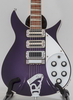
My Rickenbacker 350 Liverpool from 1995 had 3 of the mid period Hi Gains - the pole pieces without any hex holes. I have no major tooling nor a vice, so I used hand tools and a Dremel to remove the button tops of the pole pieces in order to put toaster tops onto the Middle and Neck. The reason I did all this work to my existing pickups instead of some current models with more easily removed hex-pieces is because the black plastic toaster "holes" on these do not have that extra little circle of plastic on each end. I think its a cleaner look. Looking back, I should have sent them out to have countersunk flat-top screws put in.... but then I couldn't have had all this fun!
Disassembly
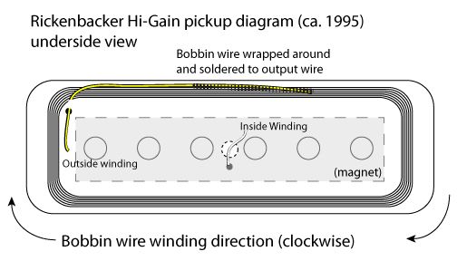
After moving the R-tailpiece away (with all the loosened strings attached) and removing the pickguard, I cut the pickup wires at the control assembly. I took out the pickups and removed the top & bottom pickup covers to free the bobbin, and cut the thick shielded extension wires as far from the bobbin as possible, so I could easily reattach my wire later. I then cut through the glue around the magnet edges with an exacto knife. The magnet itself is really soft, and I could have easily cut chunks of it off. There was a good amount of glue actually under the magnet, and I slid the knife right under to free it up. Some of the magnet material was still held by the glue, I scraped it off the bobbin. Had to be really careful to avoid cutting through the wires in the center and the corner, they're really small. The first time, I actually did cut the corner wire, flush with the bobbin. Yipe! I carefully took the shielding tape off to see the end of the connection wire itself, and saw there was actually some slack on the ultrafine-guage winding wire based on the wrap direction, so I could pull the thicker connection wire out about 1/8" to get some length to work with. That was a huge pain, dealing with that small wire with tweezers - do whatever you can to keep some of the preexisting extension wire. Here's a diagram of the wrap direction. The yellow extension wire runs in the opposite direction of winding, and the winding wire is spiraled around it like a corkscrew and soldered to it.
Once the magnet was off, I placed the bobbin on the inside edge of a roll of duct tape (!), and pounded out the pole pieces from the underside using a finish nail press I had, one that has a spring-loaded sheath and is made to set a finish nail into a wooden molding without slipping. This has no taper, as an awl does, so I thought it would be better for getting straight through the bobbin. Turns out that bobbin material is super strong and really held the pole pieces in there. I was hammering really hard to get those pole pieces to budge, with a force that I was worried would damage the bobbin. Seems like its made of a very hard but porous plastic that was formed around the pole pieces already in place. Pole pieces have a really coarse threading (deep cuts in the threads - looks like a star when viewed from below), and thread pitch - what seems like one revolution to almost 1/2 inch of travel (very coarse). Later it seemed like I might have deformed some of the threads inside the bobbin while pounding out the pieces, because it was more difficult to screw the pole pieces back in. If I had a vice to hole them securely and therefore could tap more precisely, I think I would have avoided that thread deformation, since the pieces would have rotated slower on the way out.
Pole Pieces
I used a pair of locking pliers to hold the bottom end of the pole piece while I cut off the button top, and then cut a groove for a flathead screwdriver on that top end. I put the pliers on the edge of a bench to hold with one hand and the Dremel in the other hand. The pliers ended up being a bad idea, because they deformed the ends of the threads on some of the pole pieces, making it very difficult to use a screwdriver to get them back into the bobbin. Several of the ends were too sharp and grabbed the bobbin material too much to get back into a smooth groove. The screwdriver then ended up mangling the screw end, and I had to pound them back in from the top, the same way I pounded them out. The Dremel cutting wheel was too thick (about 1/8"), I think, because it took away alot of the metal when removing the button tops, and didn't leave enough when making screwdriver slots, so that the remaining sliver of metal deformed under pressure from the screwdriver.
I pounded or screwed in all the pole pieces until they were flush with the bottom of the bobbin, putting the slightly taller ones at the center, to account for the neck radius, but it was a difference of only 1/16" or so, not very much. All of the tops of the new cut pieces ended up below the top edge of the bobbin.
When this pickup is built in the factory, it looks like the bottom (magnet) side of the bobbin is ground down to make the ends of the pole pieces flush with the bottom of the bobbin - I saw residual sanding/grinding marks. However the magnet does not end up exactly flush and touching the pole pieces. The center wire comes out of the bobbin slightly below the actual center of the bobbin, and the hole that is centered in the magnet doesn't line up with this, so there's a tiny distance between facing surfaces of the magnet and bobbin. There was also glue in this area. When I re-assembled them, I pushed the magnet tightly down onto the bobbin in the same place it was before, wrapped it tight with an elastic band and glued around the edges, but there was still air between the magnet and bobbin.
RWRP
Before I started, I marked the visible outside of the magnets "same polarity." For the Neck pickup, I just put it back the way I found it, "same polarity" mark facing out, and put a small bead of epoxy around the outside edges of the magnet. For the Middle pickup, I put that "sp" marked side facing the bobbin, to make it Reverse Polarity. Then I connected about 12 inches of the same 2-conductor & shield wire to both pickups. For the Neck, I connected using the original wiring method: red + is the outside bobbin wire (corner hole), blue — is center bobbin wire (center hole, out from center of the magnet), shield is ground, soldered to the washer screwed onto the corner of the cover. (Originally, — and shield were soldered together; 2-conductor & shield wire makes it possible to separate these to use series and phase switches) For the Middle pickup, I swapped the + and – from the standard locations, which now finally made it RWRP. In other words, the red + wire on the RWRP pickup comes out of the bobbin where the — comes out of the normal pickup (center hole), and then treat it as a normal red + when hooking up to the rest of the guitar.
Final Assembly
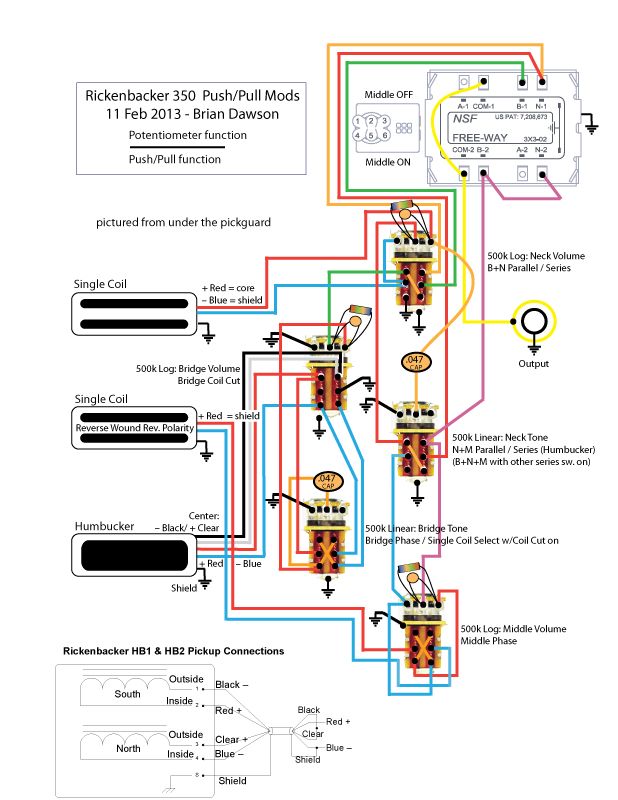
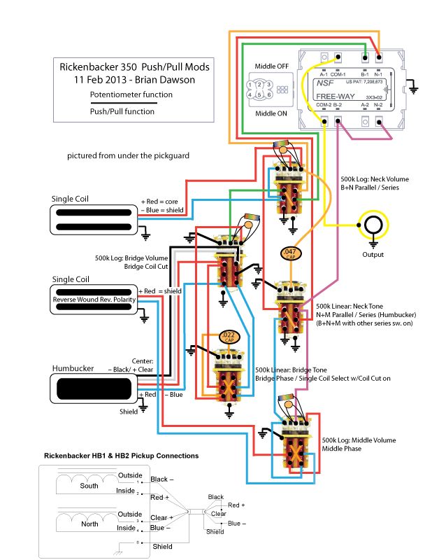
The Freeway switch 2.0 works great. I don't have experience with the V.1, but this one came from Stewmac (designed in UK) with 3 color tips, (cream, amber, & **black**), flat solder-attracting pads on the back, and small footprint. It switches smoothly, doesn't stick, and you should know where you're switching, since its not just up-n-down. It seems pretty strong, but I'm not about to hit it to see if it will break. I followed the wiring instructions, and hookup was a breeze.
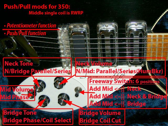
The DiMarzio 500k audio push/pulls just fit the cavity depth (there is no lower tab that adds 1/16" like on Alphas), and replicate the firm turning action of standard RIC knobs. They are a narrower diameter in the mounting shaft, however, and need strong tightening on the mounting nuts to hold them well enough to the plastic pickguard. The knurled ends fit the RIC knobs and allen screws fine without added sleeves. After a while I've gotten used to the resistor-altered tapers on the volumes, seems like they're doing everything between 0-3, whereas the original RIC pots were a perfect taper. I may take off the resistors to see the difference.
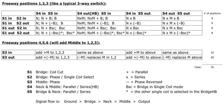
The tone controls are more interactive than I expected. The tone control of any active pickup will affect the entire sound when in Parallel mode. So whenever N is active on the Freeway, its tone control will effect the whole output, and ditto for B. I see two good things about it: 1. I have two different cap values to play with, & B. Huge sound changes are possible with one switch change. When in all-series mode, the signal path is M->N->B. The tone controls affect only the pickups before them in the series. But if B is parallel to M+N in series, then N tone will still affect B because B is in parallel. Slightly confusing, but neat effects are possible because I can use both caps at once for an ultra-cut, or different cap on either pickup (The N pickup is pretty dark, so I'm going to switch the existing .047 cap for a brighter .010 to keep some mids).
Humbucker Diagram Mistake?
The face of my remaining unaltered factory Hi-Gain is attracted to what is labeled by RIC in the diagram as the South pole face of the HB; the RWRP face is attracted to the North. Opposites attract! Therefore I thought the factory standard polarity of my 1996 Hi-Gains is North facing up, toward the bobbin, based on the new RIC Humbucker I have, its diagram, and the attraction/repulsion of the Hi-Gains to the two HB poles.
I thought I needed the Humbucker's North coil to be active, when I pulled the coil-cut switch to make use of the noise canceling of the Middle RWRP pickup (Neck:N - Mid:S - Bridge:N). I wired it so the North coil, based on the pin numbers on the RIC diagram, would be active. All the HB wire colors IRL corresponded to the RIC diagram. When I finally plugged in to check the system, the whole HB was out of phase with the rest of the guitar. I swapped the Black and Clear wires at the coil-cut switch and then it sounded as expected when switches were in all the different positions. Now the active coil in coil-cut mode sounded like it was the one closest to the bridge, with a too-harsh tone in single-coil solo mode, compared to the other coil. I spun the HB around 180º with the wiring pad away from the pick guard, on the left side of the HB when looking down from the top, so now the active coil is farther from the bridge, and is a good approximation of a HiGain. When I pull the phase/coil select switch to activate the coil next to the bridge, its a little harsh in solo, but that plays well when combined, opposite phase, with the other pickups.
Was I reading the diagram wrong? I was looking at the pickup from the top, string side up, wire pad to the right, all colors were the same as IRL. Is the N/S +/– labeling on the diagram wrong? Are all RIC HBs wired out of phase?
Here's my final as-built diagram. The HB-1 diagram is straight from RIC, uncorrected.
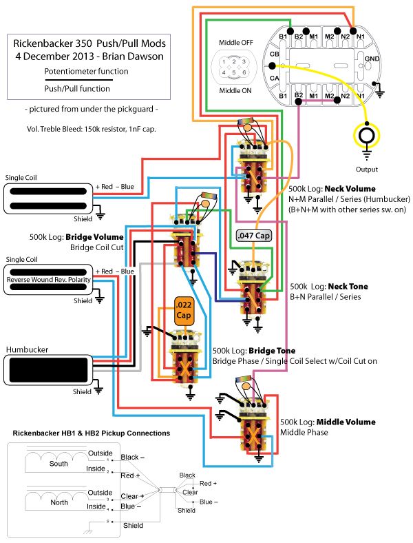
 *** Signal flow as built is: Ground > Middle > Neck > Bridge > Output ***