Need help restoring/rebuilding a Rickenbacker M11
Posted: Sat Mar 30, 2013 12:12 pm
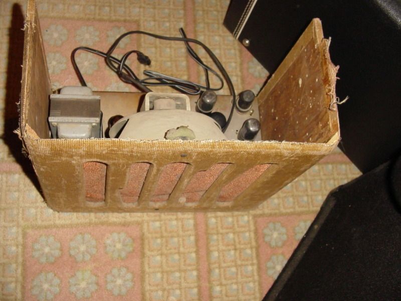
Several months ago I snagged what I think is an M11. I have looked through the Registry and it comes up as being an M11 (it was already entered in there twice I believe) and I have found the one single article on it by Dave Hunter that also calls it an M11. This is the version with the rounded top that spells RICK across the grill slats and has the upward facing controls, though the one I bought was missing the back panel to mount the chassis.
I'm not amp illiterate, especially with a schematic, but I also really need to do research to work my way back up to how these things really work if I'm doing something beyond a small mod, recap, or just tracing down a problem. I assumed that this amp would just need some bad parts replaced and now I'm finding that whoever touched it before it got to my house probably didn't just replace parts, but also didn't replace them in the right spots...at least not if the circuit used the tubes that the Hunter article refers to.
I guess to start out I'm wondering if anybody at all has any gut shots of one from this era, and then if anybody can at least tell me whether the preamp tube should be grid leak or cathode biased and what type of phase inverter this would most likely have had. I can find the M11 on the Rickenbacker site with a pair of 6SC7 tubes, but this one has a 6SJ7 pentode preamp and (supposedly) a 6SN7 phase invertor. It came to me with a 6L6 in one power tube slot, a 6V6 in the other socket, and another 6V6 in the PI socket.
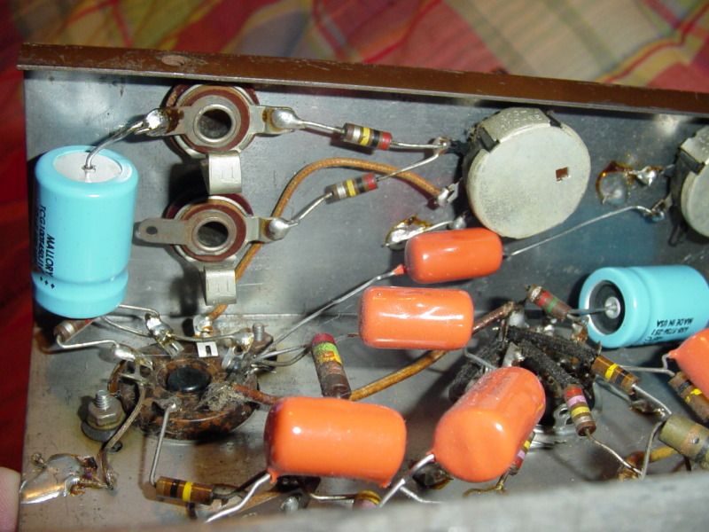
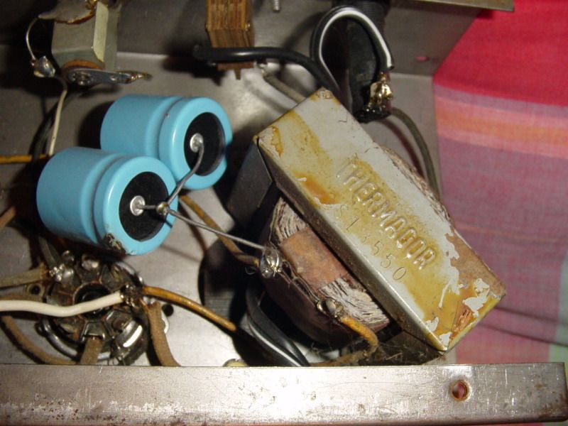
I have compared the PI to a few old schematics from the '50s with octal tubes and part of it seems to wired correctly where connecting to the output section except that those components are shifted one pin off which doesn't fit with any of the octal twin triode tubes I've found data on. I could theorize that somebody accidentally moved these over one pin except that I have no heater filaments and the heater pin that would have gone to ground seems to have at least on original component and solder joint so I'm at a bit of a loss. The power tube section looks right to me except for one oddball capacitor between the two tubes. Any kind of pictures, or at least some knowledge of what "basic" circuit design each tube used would be greatly appreciated. I could rewire it to match some other circuits, but would prefer to get closer to original if it was something unique.
I don't know if there are enough experts here to help me or not, but if nobody is familiar enough with these circuits maybe somebody can at least point me to some good research sources that may show some example circuits for these tubes or a forum that delves into the older or developmental stage circuits.
Thanks.
I'm not amp illiterate, especially with a schematic, but I also really need to do research to work my way back up to how these things really work if I'm doing something beyond a small mod, recap, or just tracing down a problem. I assumed that this amp would just need some bad parts replaced and now I'm finding that whoever touched it before it got to my house probably didn't just replace parts, but also didn't replace them in the right spots...at least not if the circuit used the tubes that the Hunter article refers to.
I guess to start out I'm wondering if anybody at all has any gut shots of one from this era, and then if anybody can at least tell me whether the preamp tube should be grid leak or cathode biased and what type of phase inverter this would most likely have had. I can find the M11 on the Rickenbacker site with a pair of 6SC7 tubes, but this one has a 6SJ7 pentode preamp and (supposedly) a 6SN7 phase invertor. It came to me with a 6L6 in one power tube slot, a 6V6 in the other socket, and another 6V6 in the PI socket.
I have compared the PI to a few old schematics from the '50s with octal tubes and part of it seems to wired correctly where connecting to the output section except that those components are shifted one pin off which doesn't fit with any of the octal twin triode tubes I've found data on. I could theorize that somebody accidentally moved these over one pin except that I have no heater filaments and the heater pin that would have gone to ground seems to have at least on original component and solder joint so I'm at a bit of a loss. The power tube section looks right to me except for one oddball capacitor between the two tubes. Any kind of pictures, or at least some knowledge of what "basic" circuit design each tube used would be greatly appreciated. I could rewire it to match some other circuits, but would prefer to get closer to original if it was something unique.
I don't know if there are enough experts here to help me or not, but if nobody is familiar enough with these circuits maybe somebody can at least point me to some good research sources that may show some example circuits for these tubes or a forum that delves into the older or developmental stage circuits.
Thanks.