

I've heard that there were various differences in the tone/volume circuitry used in the 4002 and that the schematic diagram on the RIC site isn't necessarily what was actually used. When I made the mods to my 4004Cii to add a circuit like the 4002, I followed the schematic on the RIC site, but I'm not really impressed with the results. Of course this could be that I have HB-1s and not 4002 pickups, etc., etc.
Anyway, I'm not done experimenting and will likely make a few more changes. I was wondering if any of you out there who actually have a 4002 have ever looked at the circuitry and can give me some insights as to what was actually used. Even a few pictures of the actual circuit would help as I can probably figure out what was done from that.
Also, if anyone has any idea of what the resistance measurements are on a 4002 pickup, that might help in adapting it to the HB-1 pickups.
4002 Circuitry
Moderators: rickenbrother, ajish4
4002 Circuitry
I have NO idea what to do with those skinny stringed things... I'm just a bass player...
Re: 4002 Circuitry
Jdog's 4002 that I played at the Friday evening jam at the Doubletree Hotel on 08/25/06 sounded great; it has/had HB-1s in it IIRC.
-
sloop_john_b
- Rick-a-holic
- Posts: 13843
- Joined: Tue Jan 25, 2005 6:00 am
Re: 4002 Circuitry
Jeff, that was Gary's and I believe it is stock.jps wrote:Jdog's 4002 that I played at the Friday evening jam at the Doubletree Hotel on 08/25/06 sounded great; it has/had HB-1s in it IIRC.
-
cassius987

- Senior Member
- Posts: 4723
- Joined: Mon Aug 04, 2008 2:11 pm
Re: 4002 Circuitry
Talk to iiipopes and he'll make a wiring diagram of his for you. He uses the real pickups. They're amazing. Of course I love HB-1s also.
Re: 4002 Circuitry
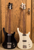
CJ, Jake has pictures up of his 4002 that is FS/FT and there are pics of the circuitry:
http://s300.photobucket.com/albums/nn10 ... lone/4002/
http://s300.photobucket.com/albums/nn10 ... lone/4002/
Re: 4002 Circuitry
Now that you mention it, you are right; I was mistaking it with that of Dave Pascoe's.sloop_john_b wrote:Jeff, that was Gary's and I believe it is stock.jps wrote:Jdog's 4002 that I played at the Friday evening jam at the Doubletree Hotel on 08/25/06 sounded great; it has/had HB-1s in it IIRC.
Re: 4002 Circuitry
I'd forgotten about that...johnallg wrote:CJ, Jake has pictures up of his 4002 that is FS/FT and there are pics of the circuitry:
http://s300.photobucket.com/albums/nn10 ... lone/4002/
That's a start, I can probably figure out something from those.
I have NO idea what to do with those skinny stringed things... I'm just a bass player...

Re: 4002 Circuitry
Aaargh, I still have not done anything with the original 4002 pickups I got. Maybe I'll take them on the trip with me. Is anyone able to do rivets? 
Re: 4002 Circuitry
I can probably do what ever you need, but you're probably not coming anywhere near "The Middle of Nowhere"jdogric12aolcom wrote:Aaargh, I still have not done anything with the original 4002 pickups I got. Maybe I'll take them on the trip with me. Is anyone able to do rivets?
Back to my wiring question, looking at the photos, from what I can tell, the wiring does follow the RIC schematic with the exception that the resistors from the tone controls to the switch are 100k not 10M as shown. That would definitely have an effect on the filter characteristics. No way to tell what the cap values are though.
So, we have info on one example. Anybody else with a 4002 up for taking a look inside theirs?
I have NO idea what to do with those skinny stringed things... I'm just a bass player...
-
rickaddict
- Senior Member
- Posts: 6163
- Joined: Mon Mar 29, 2004 7:46 am
Re: 4002 Circuitry
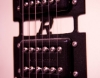
Those look similar, but the resolution isn't really high enough to tell if it's the same or different. Thanks for the pointer though...
I have NO idea what to do with those skinny stringed things... I'm just a bass player...
-
rickaddict
- Senior Member
- Posts: 6163
- Joined: Mon Mar 29, 2004 7:46 am
Re: 4002 Circuitry
There are a couple photos here http://rickresource.com/forum/viewtopic ... d%27s+4002 but the resolution isn't very high again.
I might have a photo of mine at home on my computer, but it might be a couple days before I can check.
I might have a photo of mine at home on my computer, but it might be a couple days before I can check.
Re: 4002 Circuitry
There's certainly no hurry on this since I probably won't get around to doing anything for a few weeks or more. Thanks for looking though!
I have NO idea what to do with those skinny stringed things... I'm just a bass player...
Re: 4002 Circuitry
First off, every picture I've seen that shows enough detail to make any judgments about shows the circuitry to match the RIC schematic with the exception that the "extra" resistor is 100k, not 10M. None were clear enough to see if the cap values were the same as on the schematic. I did get one response from one owner who said that his matched the schematic, I assume he meant component values as well as wiring.
OK, for all you techno-nerds out there, I've come up with some analysis of the 4002 tone circuit. I ran simulations of the circuit with both the 10M and 100k resistors. I also ran them with the tone control set all the way down, mid, and full up.
So, in the following diagram, here's what the different traces are:
Vout1(cyan): 10M, tone at min
Vout2(red): 10M, tone at mid
Vout(blue)3: 10M, tone at max
Vout4(green): 100k, tone at min
Vout5(magenta): 100k, tone at mid
Vout6(gray): 100k, tone at max
Sorry for the bad quality, I can't seem to get the plots to a file any better.
As we can see, the main difference between the 100k and the 10M is that you get more output at lower frequencies (mainly below 140Hz). With the tone full up, above 140Hz, the response is nearly identical. With the tone at mid and min positions, the curves are similar, just lower in overall volume.
So, I'm guessing that most of the 4002s actually used the 100k as this would give a better bass response and better overall output...
OK, for all you techno-nerds out there, I've come up with some analysis of the 4002 tone circuit. I ran simulations of the circuit with both the 10M and 100k resistors. I also ran them with the tone control set all the way down, mid, and full up.
So, in the following diagram, here's what the different traces are:
Vout1(cyan): 10M, tone at min
Vout2(red): 10M, tone at mid
Vout(blue)3: 10M, tone at max
Vout4(green): 100k, tone at min
Vout5(magenta): 100k, tone at mid
Vout6(gray): 100k, tone at max
Sorry for the bad quality, I can't seem to get the plots to a file any better.
So, I'm guessing that most of the 4002s actually used the 100k as this would give a better bass response and better overall output...
I have NO idea what to do with those skinny stringed things... I'm just a bass player...
-
cassius987
- Senior Member
- Posts: 4723
- Joined: Mon Aug 04, 2008 2:11 pm
Re: 4002 Circuitry
This is why Scott Pope did some mods on his 4002. And they really opened the thing up... You could e-mail him a schematic if you like.cjj wrote:So, I'm guessing that most of the 4002s actually used the 100k as this would give a better bass response and better overall output...