4002 Data

Vintage, Modern, V & C series, Fretless, Signature & Special Editions

Moderators: rickenbrother, ajish4

Post Reply
rickfan60
Senior Member
Posts: 5395
Joined: Sun Apr 11, 2004 5:00 am

Post by rickfan60 »

I've been gathering the parts to build the electronics in my faux thousand and two.
Image

For reference, I am using my '79 4002 and the RIC schematic for the 4002 circuit. The problem is there is one definite discrepancy and one apparent discrepancy between my actual 4002 and the RIC schematic. I am wondering if the schematic reflects a newer version of the wiring (mine is pretty early) or if the RIC schematic is in error. I suppose the third possibility is that I just can't read the damn thing and everything is alright. Image 
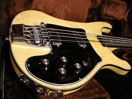
Anyway, there are resistors on the tone circuit (R5 and R6). The schematic says they are 10M Ohm resistors but the ones in my bass are clearly 350K. Can I persuade the 4002 owners out there to lift their guards and tell me the color sequence of the bands on the resistors? There should be a gold band on one end, start from there and list the colors you see. Also, you will notice some odd looking caps connecting the tone pots to ground. The cap value is molded into the cap on the side facing the pickguard. Carefully bend them up a bit to take a peek. A small mirror-like surface placed under the cap will work if you can read backwards. Here is a picture showing the resistors circled in red and the caps in blue.

Image


Please only do this if you are comfortable with it. I certainly understand if you may be a little squeemish. Any feedback on this would be greatly appreciated!
40014002
New member
Posts: 92
Joined: Sat Feb 15, 2003 6:00 am
Contact:

Post by 40014002 »

Ted I will get on it right away just give me a little while and I will take some pictures and post them.

have a good new year and I look forward to seeing the project finished.

all the best Dave Carr
Keep Music Live
40014002
New member
Posts: 92
Joined: Sat Feb 15, 2003 6:00 am
Contact:

Post by 40014002 »

Ted here we go the colours on the resistors are as follows:

GOLD
YELLOW
BLUE
GREEN

But the resistors are cream in colour where yours are red if this makes a differance.

As for the cap value is says on one side:

ITT-CB PMT/2R
And on the other:
-1 250K

I do hope this helps Ted if you require any more info or pictures let me know all the best

Dave Carr
Keep Music Live
40014002
New member
Posts: 92
Joined: Sat Feb 15, 2003 6:00 am
Contact:

Post by 40014002 »

Image
Keep Music Live
40014002
New member
Posts: 92
Joined: Sat Feb 15, 2003 6:00 am
Contact:

Post by 40014002 »

Image
Keep Music Live
User avatar
marc61
Senior Member
Posts: 6443
Joined: Sat Aug 09, 2003 9:31 am
Contact:

Post by marc61 »

Ted, when you are done, will you be writing a faux too book?
" It's not where you are, it's who you're with.".
316mark
New member
Posts: 19
Joined: Sun Feb 09, 2003 7:11 pm

Post by 316mark »

350K would be a non-standard value. Use this chart:

Image

So Dave's resistors are 560K.

A 250K cap usually means 25pF with a 10% tolerence, but it depends on the manufacturer. The 3rd number is the mulitplier, but some use it to designate 250pF.
User avatar
jps
RRF Consultant
Posts: 37496
Joined: Wed Feb 12, 2003 6:00 am

Post by jps »

Welcome Mark!


Ted,
I will check mine once somebody is kind enough to send me one! Image
rickfan60
Senior Member
Posts: 5395
Joined: Sun Apr 11, 2004 5:00 am

Post by rickfan60 »

Sh*t, I mistyped. Sorry. My resistors are in fact 300K. The colors are orange (3), black (0), yellow (4 zeros).

Thanks David and Mark. David what year is your bass?
jwr2

Post by jwr2 »

If I were doing that project I would probably use standard 4003 wiring with all 250k ohm pots or a simple vvt wiring ...
User avatar
jnbass
Veteran RRF member
Posts: 5359
Joined: Mon Mar 05, 2001 7:58 am

Post by jnbass »

use faux values...
Buy it before someone else does
gregson1
Veteran RRF member
Posts: 136
Joined: Mon Jan 15, 2001 7:14 pm

Post by gregson1 »

I'm game. It's been awhile since I've peeked inside.
Image

Image

Image

Image

Image

Hope this helps.
rickfan60
Senior Member
Posts: 5395
Joined: Sun Apr 11, 2004 5:00 am

Post by rickfan60 »

Thanks Greg. Your resistors match mine. I wonder why David's are 560K, ours our 300K and the schematic says they are 10M?

The reason why I am taking the time to work out the circuit is because the tone range of the 4002 is superior to that of the 4001/3. The highs and lows are so much better. I want to recreate as much of the 4002s sound as possible. HB1s (as good as they are) on their own just won't cut it.
gregson1
Veteran RRF member
Posts: 136
Joined: Mon Jan 15, 2001 7:14 pm

Post by gregson1 »

Ted--I see the .1uF caps (C3 & C4) going from the the tone pots to ground, the .01uF caps (C1 & C2) in parallel with 300K Ohm resistors (R5 & R6). R5 & R6 in the official Rickenbacker schematic show 10M Ohm resistors, which are the two obvious discrepancies I see. I really have no idea the resistance values for the tone and volume pots and I'm not too jazzed about unsoldering them to check.
gregson1
Veteran RRF member
Posts: 136
Joined: Mon Jan 15, 2001 7:14 pm

Post by gregson1 »

The green and blue wires go from the treble pickup to the XLR input. These leads are not present on the bass pickup. I don't know if there are two different pickups on a 4002 or if this is simply another tap available on both pickups.
Image
Post Reply

Return to “Rickenbacker Basses: by Joey Vasco & Tony Cabibe”